Geovision GV-COM PTZ Camera Setup 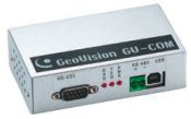 The Geovision GV-COM module can be used with a Geovision camera system to control PTZ cameras. These setup instructions cover how to set up our PTZ security camera to be controlled by one of our GV-COM modules. The GV-COM module has RS-485 inputs that are used to connect your PTZ cameras to Geovision. RS-485 is a communication protocol for cameras and other devices. If you are using a PTZ camera other than the one that we have documented in this article, you can still follow the steps of these instructions but the protocol and baud rate that you configure may be different depending on the type of PTZ camera that you are using and the baud settings that are supported by your particular PTZ camera. The Geovision GV-COM module can be used with a Geovision camera system to control PTZ cameras. These setup instructions cover how to set up our PTZ security camera to be controlled by one of our GV-COM modules. The GV-COM module has RS-485 inputs that are used to connect your PTZ cameras to Geovision. RS-485 is a communication protocol for cameras and other devices. If you are using a PTZ camera other than the one that we have documented in this article, you can still follow the steps of these instructions but the protocol and baud rate that you configure may be different depending on the type of PTZ camera that you are using and the baud settings that are supported by your particular PTZ camera.
PTZ Camera SetupFirst, follow these instructions to setup the PTZ camera. This link will open up a new browser window so that you can easily resume instructions on this page after the camera is configured.
PTZ Camera Setup
Geovision GV-COM InstallationThese instructions assume that you are setting up camera ID #1 or that you are only using one PTZ camera in your system. If you are setting up more than one camera, the ID that you configure may not be 001 as described below. The Geovision GV-COM module is easy to install on your computer. The card simply connects to any open USB port and some software drivers need to be installed that are included on a CD with your GV-COM device.
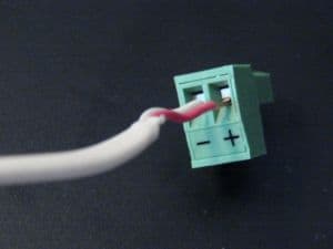
- Connect one end of the RS 485 wire (one end should already be connected to your PTZ camera) to the RS-485 +/- inputs on the GV-COM module. The small plastic green housing of the RS-485 inputs on the GV-COM can be removed to more easily let you install and screw down your wiring. You can see this below.
- Insert the RS-485 connector back into the GV-COM device if you removed it to install the wiring. This should look similar to below when done.
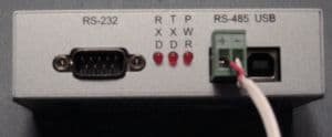
- Connect the GV-COM box to your computer using the USB cable that was supplied.
The screens and instructions are slightly different depending on whether you are using Windows Vista or Windows XP. Please follow the appropriate instructions below.
- Windows Vista should detect the device and display the following screen.
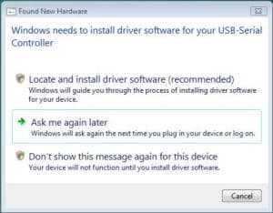
- Insert the GV-COM software CD into your Geovision computer and click the Locate and install driver software on the screen. This is the CD that says GV-COM driver on it. Windows will then install the GV-COM driver on to your computer and display a screen telling you which port the GV-COM module is installed on. Make note of this port.
- To verify the installation and to see the COM port click on the Windows Vista start button and select control panel.
- On the control panel screen switch to the Classic View and select Device Manager as seen below.
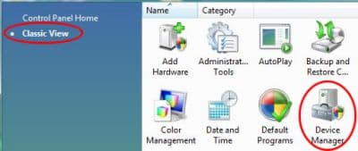
- On the Windows device manager screen, expand the Ports (COM & LPT) section and look for "Prolific USB-to-Serial Comm Port. Note the port number. In this case, COM4.
- You can now close the Windows device manager.
- After you connect the GV-COM to your computer via the USB cable, Windows XP should detect the device and display the following screen. We will not use the Windows New Hardware Wizard to install GV-COM. Click on the cancel button.
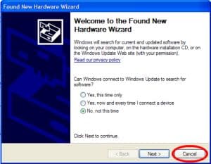
- Insert the GV-COM software driver CD into your Geovision computer. If the CD does not start automatically run the GvUsb.exe program on the CD.
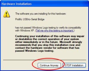
- When you run the program, the following screen will appear. Click Continue Anyway.
- To verify the installation and see which port the driver was installed to click on the Windows XP start button, then select Control Panel.
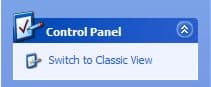
- If your control panel is not in classic view, please switch to it by selecting Switch to Classic View as seen below. If you are already in classic view, it will say Switch to Category view.
- Double-click on the System icon.
- Select the Hardware Tab and click on the Device Manager button.
- Expand the Ports section by clicking on the plus sign next to it. Look for the Prolific USB-to-Serial Bridge and note the port number. In this example COM7

Geovision PTZ Camera ConfigurationIf you have not already done so, boot your Geovision computer and open the Geovision system. To configure your PTZ camera to be controlled by Geovision follow these steps.
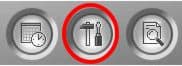
- Click on the configure button on your Geovision system (seen below) and select System Configure.
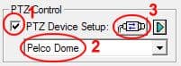
- Under the General Settings tab, there is a PTZ Control section. 1) Check the PTZ device setup checkbox, 2) Select Pelco Dome, 3) Click on the connect button as seen below.
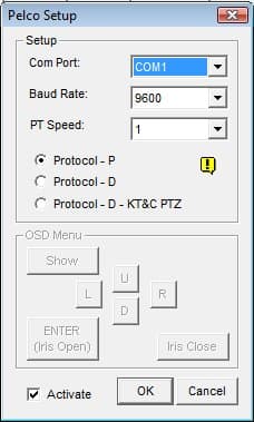
- When you click on the connect button, the below window opens to configure the PTZ camera protocol and baud rate. Set the Com port to the port that you previously noted in the Windows device manager, Baud Rate to 9600, PT Speed to 1, select Protocol - P, and check the Activate checkbox as seen below. Then click OK.
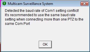
When you click OK, you may see the following baud rate warning on the screen. You can ignore this message and click OK.
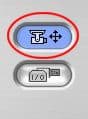
- On the main Geovision system screen, you should now see a button to gain control of your PTZ camera(s). Click on the button as seen below.
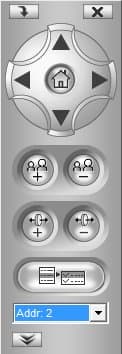
- This will open the PTZ controls on your Geovision system. Select the address of your PTZ camera that you earlier set up on your camera from the drop-down box.
You should now be able to control your PTZ camera using Geovision.
|