CAT-5 Wiring Diagram & Crossover Cable Diagram
This
CAT5 wiring diagram and crossover cable diagram will teach an installer how to correctly assemble a CAT-5 cable with RJ45 connectors for regular network cables as well as crossover cables. Please note that these instructions are the same for CAT-6 cable and and other type of 4 twisted pair network cable. Please also note that in this article, we are referring to CAT5e, CAT5, and CAT-5 as all the same type of cable. CAT5 Ethernet cable.
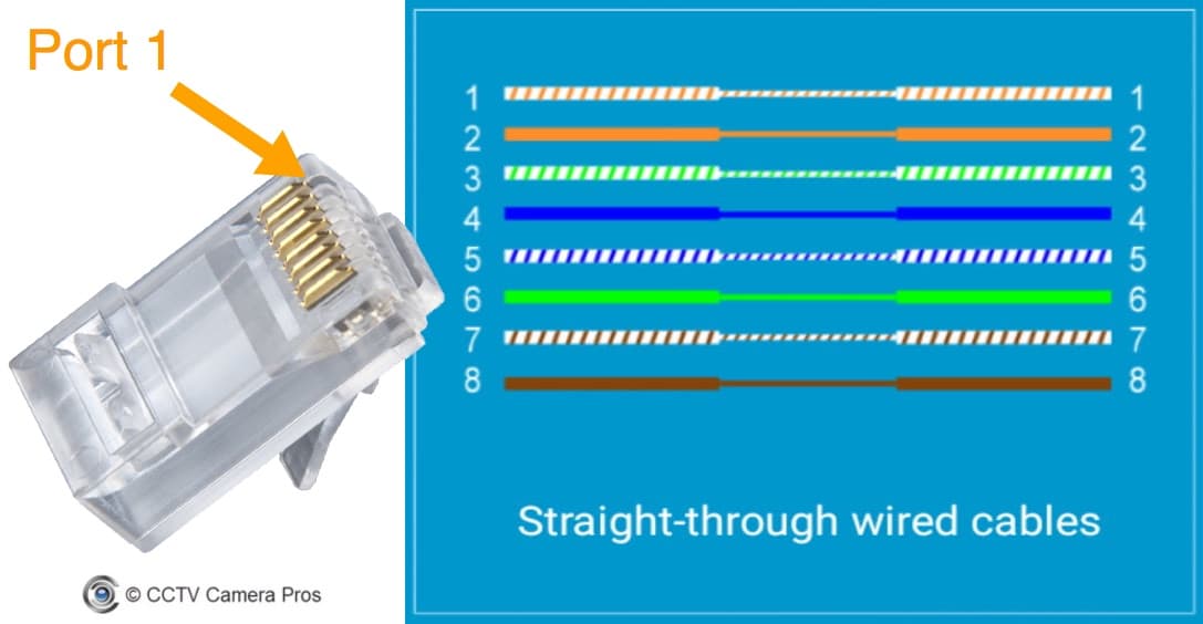
This diagram shows the sequence of colored wires used for EAI standard Ethernet cable / TIA-568B. Please note the CAT5 wire order. It must be consistent on both ends of the cable.
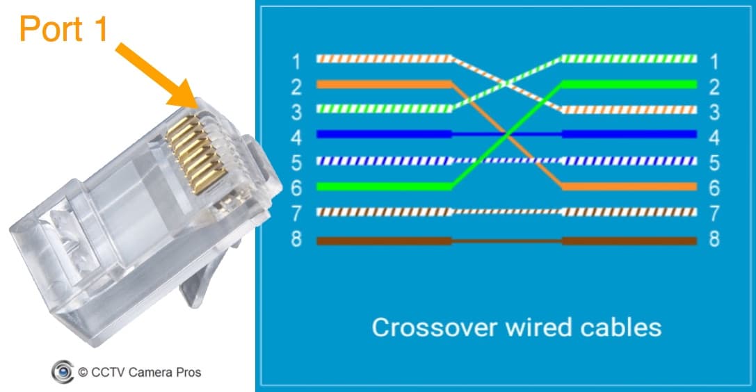
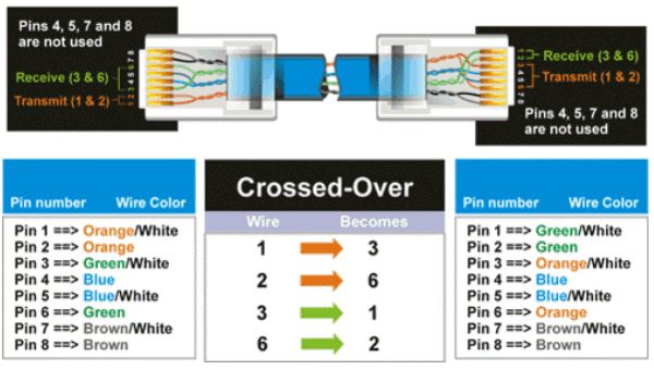
This diagram shows the sequence of colored wires used for EAI cross-over cable / TIA-568A standard. Please note the CAT-5 wire order.
CAT-5 Cable Installation
EIA/TIA-568B, also known as standard Ethernet, is the type of CAT-5 connection used to connect
IP security cameras and network video recorders (NVRs) in IP surveillance systems. If you are creating a crossover cable, please click here for the crossover cable diagram.
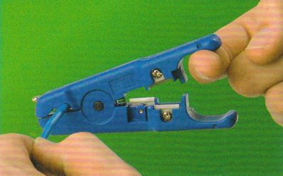
- Using a cable stripping tool, strip about 1/3"of the out jacket of the cat-5 cable. Be sure not to strip or damage any of the pairs of inner cables.
- Assemble the pairs of wires in the following order for network cables (EAI standard / TIA-568B).
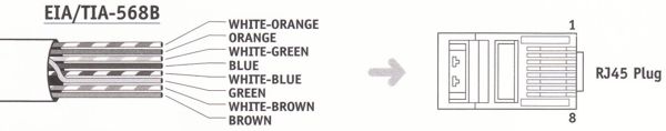
- Insert the wires into the RJ45 jack as seen below. Be sure to keep the wires in the correct order.
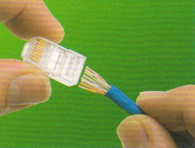
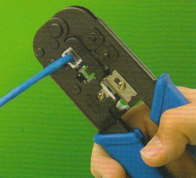
- Insert the RJ45 connector into the crimping tool (again carefully make sure the wires stay inserted in the correct order). Crimp down firmly on the crimping tool to permanently attach the RJ45 to the CAT5 cable.
Crossover Cable Diagram
To create a crossover cable with cat-5 cable follow the same instructions as above for
CAT-5 wiring except when you get to step #2, use the below crossover cable diagram:

|
Author
This article is maintained by
Mike Haldas, co-founder and managing partner of CCTV Camera Pros. Questions about this page can be directed to mike@cctvcamerapros.net.
|
|
CCTV Equipment
|
Video Surveillance Systems
|
Network Surveillance Equipment
|
|
|
|
|
|
|
|